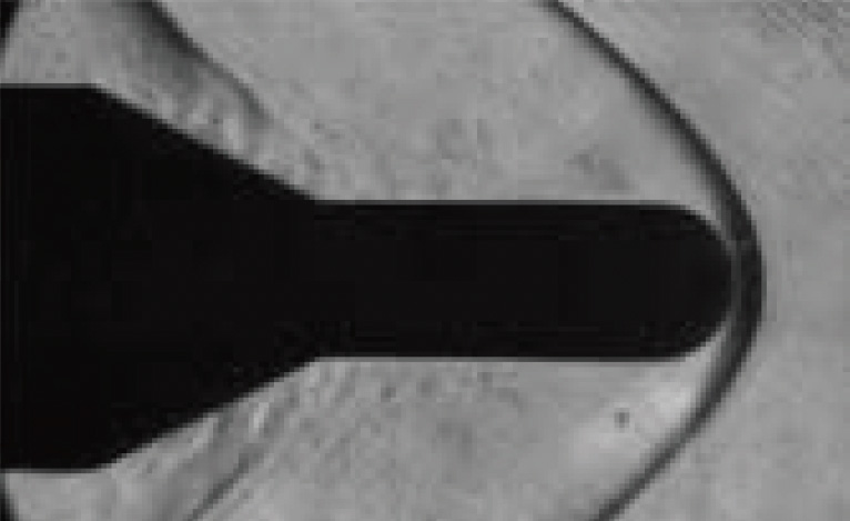

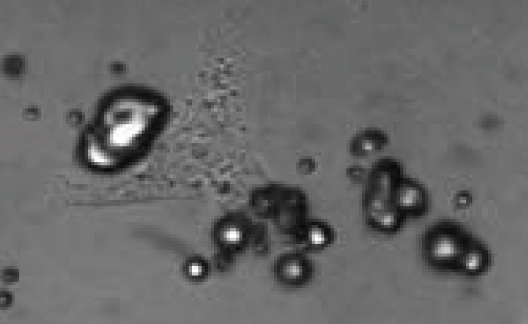

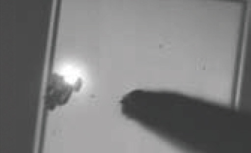


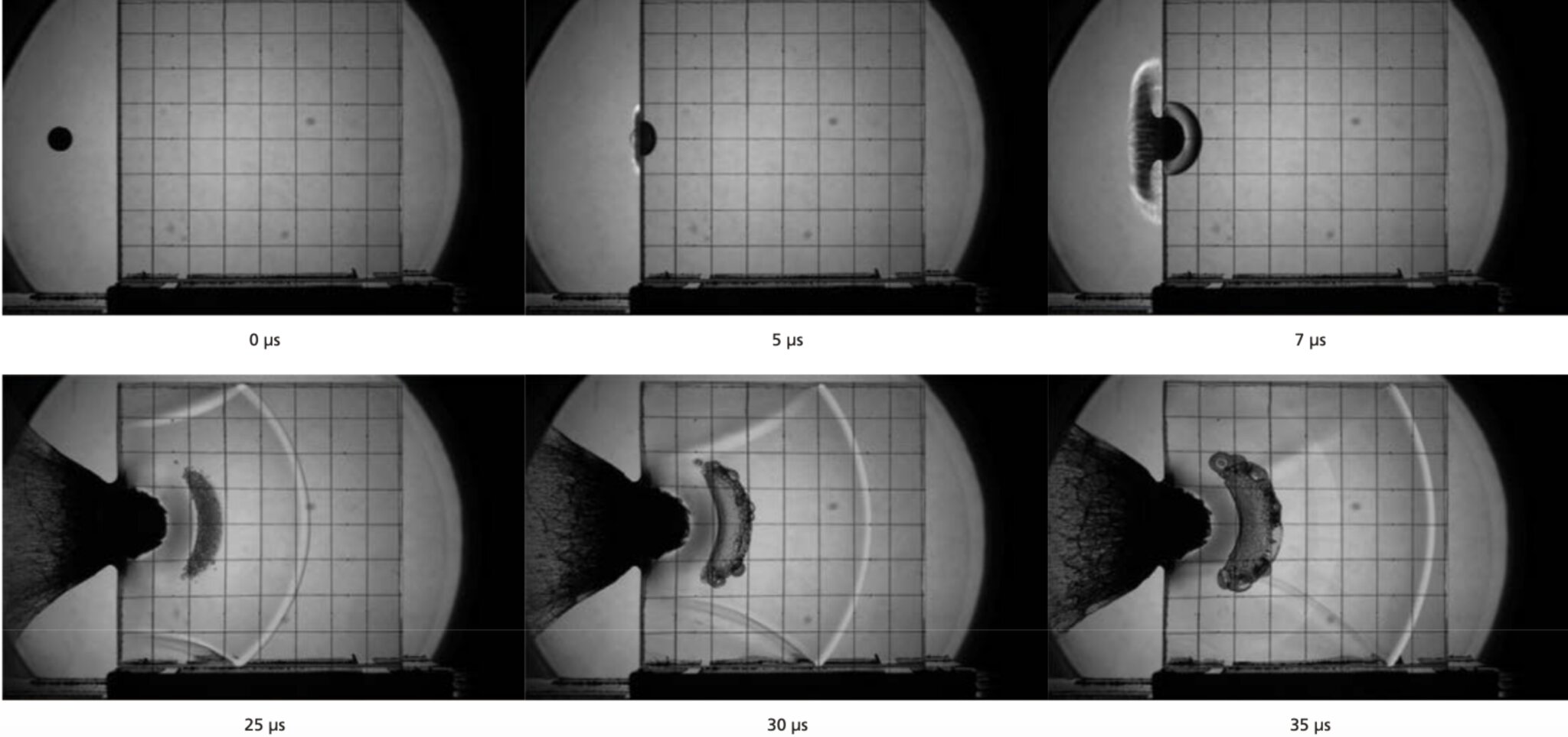
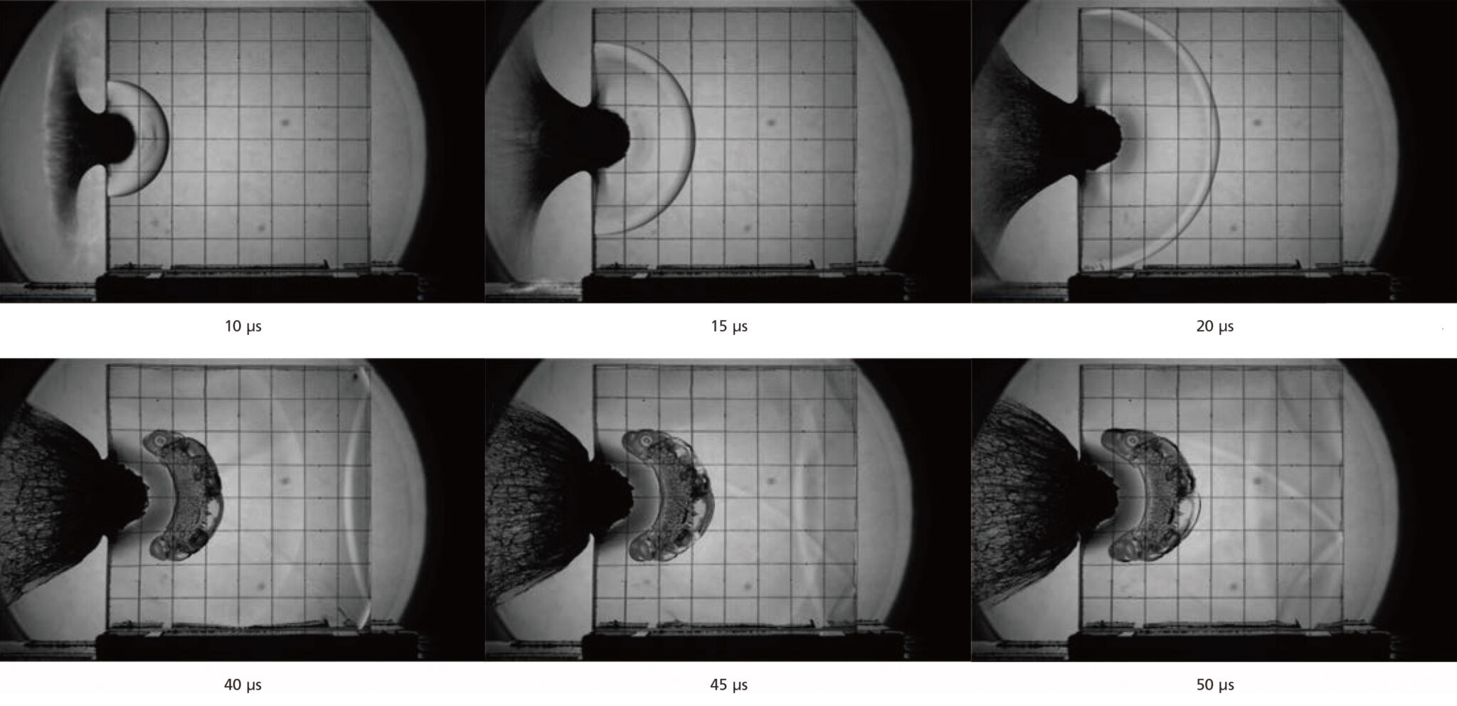
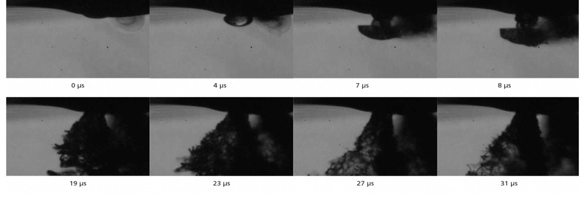
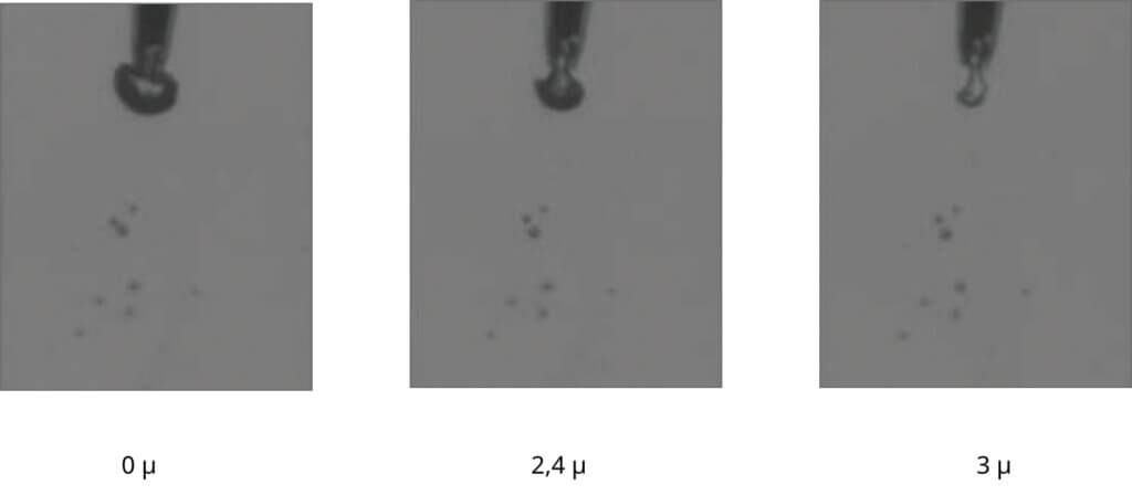
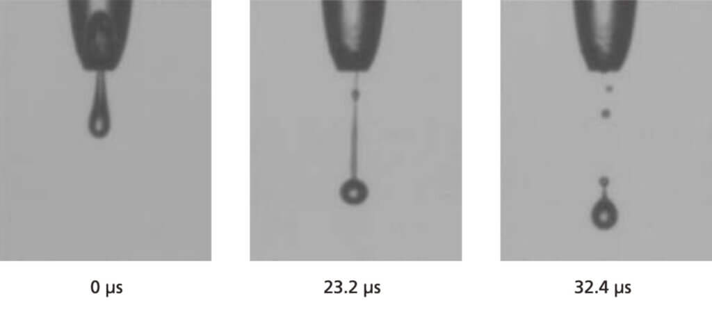
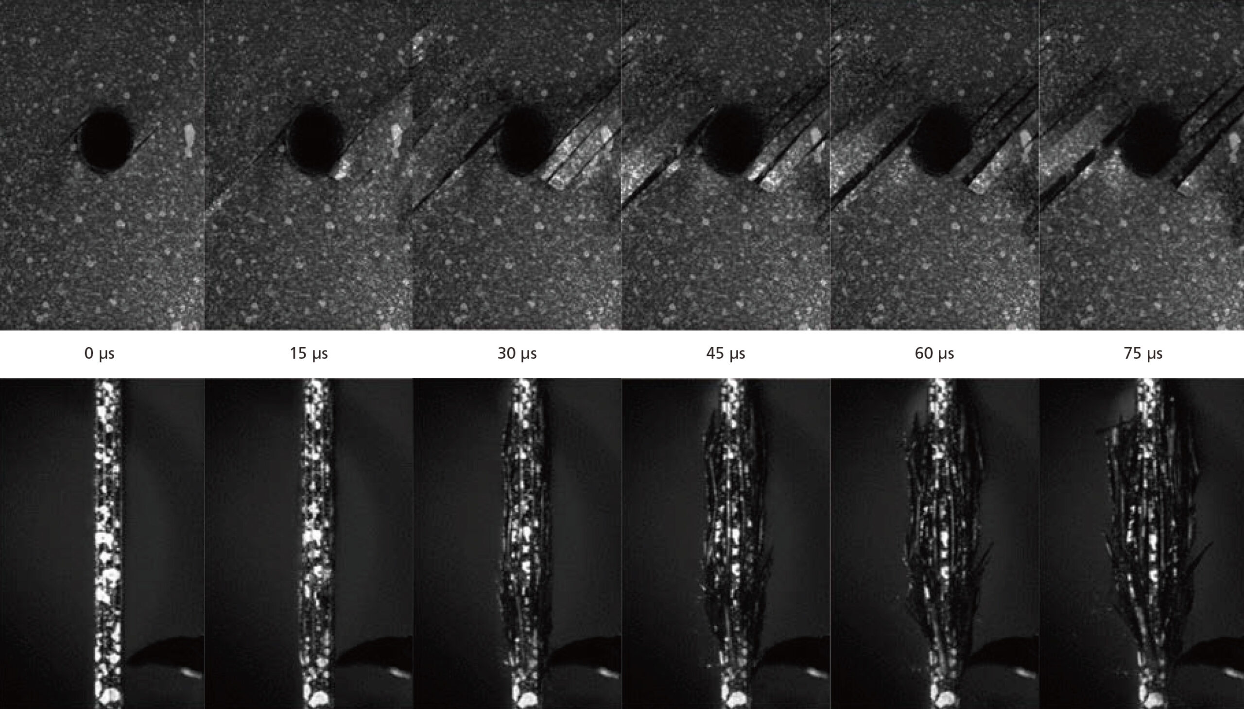
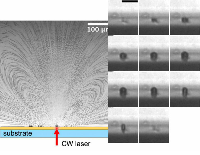
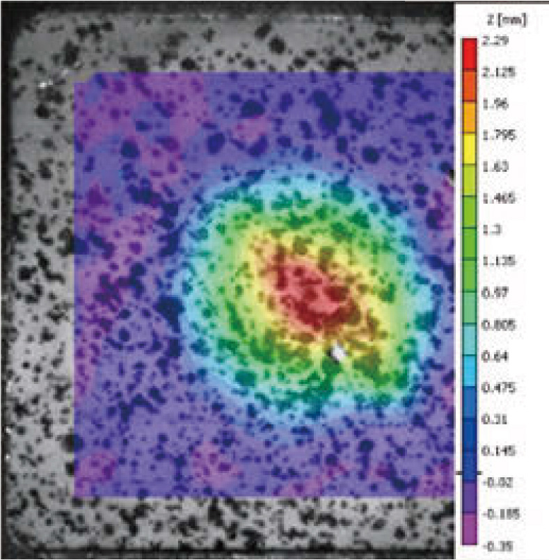
Width of field of view: Approx. 0.8 mm


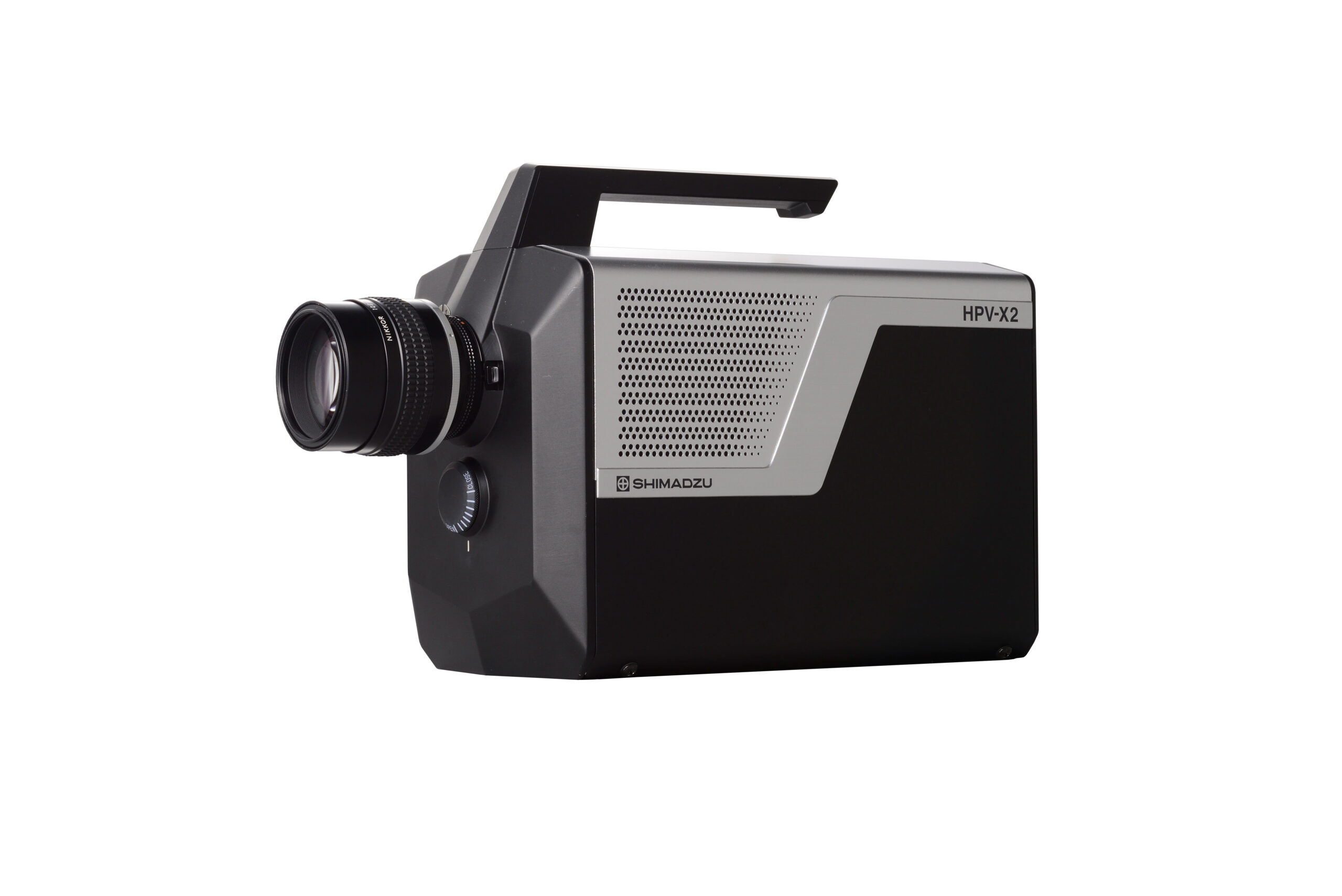 | ||
| Hyper Vision HPV-X2 | ||
|---|---|---|
| Camera Head | ||
| Lens Mount | Nikon F-mount1) | |
| Image Sensor | FTCMOS2 image sensor | |
| Recording Speed2) (frame rate) |
|
|
| Continuous Recording Capacity |
|
|
| Resolution |
|
|
| Color/Gradations | Monochrome, 10 bits4) | |
| Exposure Time5) |
| |
| External Trigger Input | Two channels (TRIGIN, STANDBY) TTL level (5 V), capable of either positive or negative polarity | |
| Recording Mode | Internal trigger, external trigger, continuous trigger | |
| Synchronization Function | Capable of synchronized recording with two cameras connected | |
| Optional Outputs | Two channels (exposure start timing, trigger detection timing, or other outputs depending on settings) | |
| Trigger Point Setting | Can be set to any frame from the second frame onwards. | |
| Interface | One 1000 Base-T/100 Base-TX port | |
| External Monitor Output6 | NTSC/PAL output | |
| Data Memory Format | 10-bit dedicated format, BMP, AVI, JPEG, TIFF (8-bit and 16-bit formats supported) | |
| Power Supply Unit | ||
| Power Rating | Single phase 120 V/220-230 V, 200 VA, 50/60 Hz | |
| Required Specifications for the Control PC | ||
| Operating System | Windows10 Pro7) (64bit) | |
| CPU | Intel Core i5 or faster | |
| Memory | ||
| HDD | 250 GB or more | |
| Screen Size | 1,366 × 768 or larger | |
| Interface | 1000 Base-T/100 Base-TX | |
| External Recording Device | DVD-RW | |
| Other Peripherals | Mouse and keyboard | |
| Environmental Conditions | 4 GB or more | |
| Operating Temperature Range | 5 to 40 °C | |
| Operating Humidity Range | 35 to 75 % RH with no condensation | |
| Storage Temperature Range | 0 to 50 °C | |
| Storage Humidity Range | 20 to 80 % RH with no condensation | |
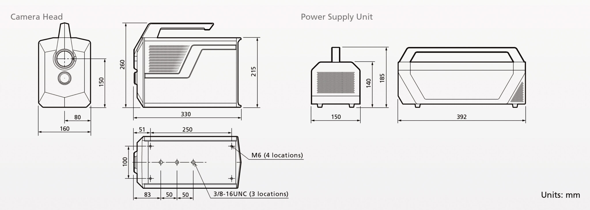
| Size and Weight | ||
| Camera Head | W160 × D330 × H260 mm, approx. 6.4 kg | |
| Power Supply Unit | W150 × D392 × H185 mm, approx. 5.2 kg | |
| Length of Interface Cable Between Camera and Control Computer | Approx. 2 m | |
| Length of Cable Between Camera and Power Supply Unit | Approx. 2.8 m |